2018/09/26 ~ 10/05 몰디브여행


결혼하고 푸켓 신혼여행때
'우리 결혼 10주년에는 몰디브 한번 가보자' 했던,
와이프와의 10여년전 약속을 지켰다.
그 사이 생겨난 딸아이 둘과 함께...


한국에 도착하자마자
니글니글한 속을 달래주기위해
순식간에 흡입한
짬뽕 한 그릇에  막걸리 한 병
(인천공항 제2터미널 푸드코트)


늬들이 이 물속에서 오줌싸는 기분을 알아?


또 가고 싶다 몰디브...

뭘까?


블로그 설정 화면에서 내 블로그를 방문하는 사람들의
접속 국가별 페이지를 제공하는데,
가끔씩 저렇게 러시아 접속자가 많을 때가 있다.
생각해 보니 자주인거 같기도...

뭘까?

러시아어로 써놓은 게시물도 없고,
영어로 써놓은 게시물이 많지도 않은데...

러시아 거쳐서 오는 사람들인가?
러시아에 우회 서버가 많은가?
정원이 인가?
갑자기 무서워짐
난 콩사탕이 싫어요!!~~

Sigma EF-500 DG SUPER MA(Minolta) Modification for the Pentax Hot Shoe Mount

이번 삽질도 아트와 관련된 거다.
내가 원래 아트에 관심이 좀...

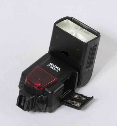
재활용 쓰레기통에서 망가진 외장 플래시를 구했다.
모델명은 'Sigma EF-500 DG SUPER MA'로 보인다.
확인해 보니 플래시 램프가 타버렸다.
가지고 있는건 펜탁스 카메라인데, 이건 Minolta 마운트용이다.
[Fig. 1] 처럼 생겼다.

I've finished the conversion of the 'Sigma EF-500 DG SUPER MA' Minolta hot shoe mount into the Pentax hot shoe mount. And I'll describe what I've done about it.
My Sigma EF-500 DG SUPER MA's flash lamp was burned out so doing the lamp replacement is initial process and then, I have to modify mechanical-mounting followed by electrical-mounting.
I did not took pictures during the flash lamp replacement.


[Fig. 1 Sigma EF-500 DG Minolta Mount]

펜탁스에 붙여서 사용하려니 3가지 작업을 해야한다.

1. 타버린 램프를 교체
2. 기계적 마운트롤 교체
3. 전기적 마운트도 교체

음.. 일이 많다.
가지고 있던 싸구려 외장 플래시에서 램프를 빼내어 교체작업을 한다.
플래시 분해는 아래 사이트를 참고 했다.

You can refer to below link to disassemble the strobe.

Repairing an erratic Sigma EF500 DG ST
(Thank you weijen)


[Fig. 2 Extracted Burned Flash Lamp]


[Fig. 3 Hot Shoe Mount Replacement]

교체후 타버린 플래시 램프 사진만 찍었다
램프 교체하고 테스트를 해보니 동작은 잘 된다.
기계적 마운트역시 가지고 있던 외장 플래시에서 마운트 부분을 떼어내 붙여 준다.
자, 이제 전기적 마운팅을 해줘야 하는데 자료를 뒤져 보니 이거 만만치가 않다.
그냥 strobe signal을 접지 시키면 될 줄 알았는데 그렇지가 않다.
특히나 Minolta 방식이 까다로운가 보다.
전기적 마운팅을 위해 아래 3개 사이트를 참고 했다.

I've checked it works well after repairing the flash lamp, and have modified the mechanical mount with parts from my cheap external strobe for the Pentax.
Next step is just electrical-mounting but I've been aware of danger of this job. There are no easy way to trigger this strobe manually just like shorting the fire signal to the ground.
I've found out very useful 3 links bellow for this.

adrian        : Hacking the Sigma EF-500 DG Super strobe Part 1/2
Kimmo Kulovesi: Sigma EF-500 DG Super PC-sync port modification
Impulsite     : Sigma EF-500 DG ST, есть схема
(Thank you adrian, Kimmo Kulovesi and Impulsite)

adrian 링크는 수동으로 플래시를 동작 시키기 위해 겪은 시행착오를 공유해 놓은 내용이고 Kimmo Kulovesi 링크는 adrian의 시행 착오에 15nF 커패시터를 추가하여 개선했다는 내용이다. Impulsite 링크는 플래시 회로도를 공유해 주었다.
3명의 자료 공유 덕분에 내 작업이 비교적 순조롭게 진행 될 수 있었다.
얼굴도 모르는 세계의 3분에게 다시한번 감사드린다. 소중한 시간을 아낄 수 있었다.

I think the adrian is a pioneer of the Sigma EF-500 DG modification. He suggested really good idea for manual trigger through the optical-slave mode of the strobe and this method works well. All images are broken when I visit the adrian's site, but you can search images by image-googling with 'Hacking the Sigma EF-500 DG Super strobe' key words.
Kimmo Kulovesi improved the unstable behavior by attaching 15nF capacitor for bypassing noise, also very nice recommendation.
Impulsite's web is very useful with strobe's schematics.
I could make a conversion into the Pentax mount successfully by these informaion only in 2 days. I hope to say thank you adrian, Kimmo Kulovesi and Impulsite again, you saved my time.
Additionally, I performed several invetigation and experiments to make it clear. When I shorted the photo-diode's anode and cathod, large current was observed by probing the voltage drop with my strobe, so I added current limiting register in my final result, R1 in [Fig. 7].
General Si. photo-diodes let current under 100uA, typically 50~60uA, when detected the light.
The main CPU should observe the delta-voltage, approximatly under a hundred micro-volts to detect the light if there is no signal amplification.
I found that the photo-diode's singal (anode) is routed to the main CPU(?) directly, it's means that the main CPU(?) may detect under 100uV of delta-volts to sync with light signal when it's in optical-slave mode.
The strobe's unstable behavior (without Kimmo Kulovesi's 15nF capacitor) could be explained by this measurement mechanism. If you extended the photo-diodes's signal wire (anode), even small disturbances could influence the delta-micro-volts detection loop so the Kimmo Kulovesi's 15nF capacitor is very important.
To protect DSLR camera I attached the opto-coupler PC817.
You should short pin 5 and 6 to work properly in optical-slave mode. refer to [Fig. 8].
My Pentax camera and the modified Sigma EF-500 DG SUPER MA works perfectly togather in "C0 SL" mode.

요약하자면 다음과 같다.

1. Sigma EF-500 DG SUPER는 단순 단락으로 플래시 동작이 안된다.
2. optical-slave모드에서 내부 photo-diode 신호를 변형해 동작이 가능하다.
3. photo-diode 신호 변형을 위해 wire를 인출 하면 동작이 이상해 진다.
4. 인출된 wire에 커패시터를 부착하면 사용가능한 수준이 된다.

adrian이 말한대로 photo-diode에서 선을 빼내면 수동으로 동작이 가능하지만, 가끔 플래시가 먹통이 된다. 이를 위해 Kimmo Kulovesi는 신호선에 15nF 커패시터를 달아 해결하였다.
Impulsite의 회로도를 참고해 나름 테스트를 해본 결과 photo-diode의 신호를 메인 CPU(?)에서 입력 받는 구조인데, photo-piode의 전류 신호가 수십 uA대로 작다 보니 측정되는 전압의 변화 역시 수십uV 수준이다.
외부에 선을 달아 주게 되면 안테나 역할을 하게 되면서 외부 노이즈가 유입되어 플래시 커패시터의 방전과 충전이 반복되면서 기기가 먹통이 된다.
처음에 adrian이 소개한 대로 photo-diode의 선을 인출 하여 쇼트시켜보니 동작은 하는데 전류가 많이 흐르는듯 하다. 하여, 아래와 같이 카메라도 보호할 겸해서 opto-coupler를 추가로 장착하여 카메라와 연동하는데 성공 했다. [Fig. 7]에서 추가한 R1은 과전류 보호용이고 R2는 opto-coupler의 발광 다이오드 구동용이다.
optical-slave 모드로 동작 시키기 위해서는 [Fig. 8]과 같이 커넥터 5번과 6번을 쇼트 시켜야 한다.
플래시의 발광량 가변이 되니 신세계다.


[Fig. 4 Power board, Pic. from Impulsite]


[Fig. 5 Power board Schematics, Pic. from Impulsite]


[Fig. 6 Photo-Diode Polarity, Anode(A) and Cathod(C)]


[Fig. 7 Modification Schematics]


[Fig. 8 Connector Modification]

Hot shoe connector pin out
  - 1  : F2 (READY)
  - 2  : F1 (SYNC/FIRE)
  - 3  : GND
  - 4  : F3 (TTL OK)
  - 5/6: Shoe Mount Detection (contacted together when demounted)
  - 7/8: LED

[Fig. 9 Wiring]


[Fig. 10 Final Result]

사진은 안찍고 이런거나 만들고 있음.

DIY Footswitch for the Line6 POD

역시 간만에 또 글을 쓰는군.
이번 삽질은 아트와 관련된 거다.
전기기타 멀티이펙터용 풋스위치.

얼마전 Line6사의 POD 전기기타용 멀티이펙터(정확한 명칭은 앰프 시뮬레이터라고함)를 구했다.
꾹꾹이만 쓰다 멀티이펙터를 사용해 보니 우와 편하고 좋다.
근데 풋스위치가 없어서 좀 불편하다.
검색해 보니 누군가 POD의 풋스위치 인터페이스에 대해 나름 숭고한 삽질의 결과를 친히 공개해준 자료가 있어 많은 도움이 되었다.

In this text, I hope to share my private project result 'DIY Footswitch for the Line6 POD' which was motivated by Mark Lavelle's great effort and time sharing.

http://harmonicappliances.com/floorboard/floorboard.html
(시간과 노력을 공유해준데 대해 대단히 감사드립니다.)
(Very very thank you Mark Lavelle for your great job and publication.)

초기 계획은 LED빼고 저항과 스위치만으로 구성하여 간단하게 맹글어 쓸려고 했는데 기왕이면 LED 불도 켜지면 좋을꺼 같고, 7-segment로 숫자도 표시되면 좋을꺼 같고해서 마침 놀고 있던 PIC18F2550을 활용해 만들었다.

풋스위치는 아래와 같이 외부에 저항만 직렬 연결하면 구성이 된다.

As described above link, footswitch functions are enough just with passive series-resistors.
===========================================================
      POD
  ----------+
            |
       5V   |
       |    |
       R=1K |
       |    |  RJ-45 pin 6
  AD(?)+-------+
            |  R1=0
  ----------+  +------SW-----GND : TapTempo/Tuner(0.04V)
               R2=100
               +------SW-----GND : ChSel/EffectOnOff(0.49V)
               R3=120(220)
               +------SW-----GND : Wah(0.90V)
               R4=150(370)
               +------SW-----GND : ChA/EQ(1.38V)
               R5=200(570)
               +------SW-----GND : ChB/TremChorus(1.83V)
               R6=240(810)
               +------SW-----GND : ChC/Delay(2.23V)
               R7=290(1.1K)
               +------SW-----GND : ChD/Reverb(2.67V)
               R8=1.6K(2.7K)
               +------SW-----GND : BankUpDown(3.65V)
               R9=1.0K(3.7K)
               +------SW-----GND : BankUp(3.88V)
               R9=1.3K(5.0K)
               +------SW-----GND : BankDown(4.1V)
               R10=15K(20.0K)
               |
              GND
===========================================================

채널 4개 선택, Bank-Up, Tuner스위치만 구성했다.
LED구동을 하려면 위 링크에 설면된 대로 POD에서 보내주는 펄스 신호의 길이를 측정해야 한다. 때문에 별도 신호처리를 위한 장치가 있어야 하는데 PIC18F2550을 활용해 SW로 처리했다.
외부 4MHz오실레이터 입력을 받아 내부 PLL에서 48MHz(최대)로 동작 한다.
POD의 신호를 외부 인터럽트나 캡쳐 기능을 활용해 시간 측정을 하려고 시도했었으나, PIC의 인터럽트 지연(interrupt latency)이 의외로 길어 1us의 펄스신호를 측정하는데 부적합 했다(라고 썼지만 코드 최적화 능력이 안된다고 해석하면 된다). 그래서 메인루프에서 폴링기반으로 신호를 측정 하도록 구성했다. 이렇게 구성하니 interrupt context switching overhead가 없으므로 1us의 펄스 측정이 가능하였다.

I integrated channel A/B/C/D and only Bank-Up, Tuner switches for simplicity.
LED driving is not simple work, this function is needed a special device to handle digital pulses. I used PIC18F2550 micro-controller-unit to process digital pulses from the POD.
My initial design was concerned about display 3-digit 7-segment that is essential the timer interrupt based dynamic drive. But the 48MHz(maximum) clocked PIC18F2550 and my C-code could not measure the 1us pulse through the external interrupt/capture because of interrupt latency(Or maybe caused by my poor code optimization skill or non-asm code-base). So I've changed interrupt based code to polling method to measure 1us POD's LED pulses.
There is no interrupt context switching overhead in the polling method and for keeping up the regular sampling time, the code should not include any interrupt.

PIC18F2550 핀맵은 아래와 같다.
PIC18F2550 pin usage is like below.
========================================
  01[VPP] :VPP         28[RB7]:PGD
  02[RA0] :SEG_A       27[RB6]:PGC
  03[RA1] :SEG_B       26[RB5]:PGM
  04[RA2] :SEG_C       25[RB4]:LED_D
  05[RA3] :SEG_D       24[RB3]:LED_C
  06[RA4] :SEG_E       23[RB2]:LED_B
  07[RA5] :SEG_F       22[RB1]:POD_IN
  08[VSS] :GND         21[RB0]:LED_A
  09[OSC1]:4MHz        20[VDD]:5VDC
  10[OSC2]:4MHz        19[VSS]:GND
  11[RC0] :SEG_G       18[RC7]:UART-RX
  12[RC1] :LED_TEMPO   17[RC6]:UART-TX
  13[RC2] :NC          16[RC5]:NC
  14[VUSB]:NC          15[RC4]:NC
========================================

PIC구성시 초기 계획은 3-digit 7-segment를 활용하려 했으나, 폴링모드로 구성하는 바람에 7-segment의 dynamic drive구현이 불가능 하여 1-digit 7-segment만 적용했다. 때문에 POD에서 날라오는 신호값을 확인하여 각 모드에서 3개 문자중 필요한 것만 표기되도록 하였다.
POD의 튜너모드에서는 'Line6 Floor Board'처럼 6개 LED가 피치값을 표기해 주도록 되어있다. 그러나 내가 만든 footswitch에는 4개 LED밖에 없어 6개 LED 피치 디스플레이를 4개 LED로 압축하여 표기되도록 구성 했다.
7-segment를 비롯해 모든 LED는 active-low로 동작 한다(0일때 켜짐).

All LEDs including 7-segment are active-low(turned on when 0V, driven by sink current).
The LED_TEMPO was connected to dot-LED of the 7-segment.
Since my footswitch has only 4 LEDs and 1-digit 7-segment display, my code check the POD's current working mode to display only 1-digit, especially in tuner mode 6-LED based pitch display is shifted 4-LED based pitch display like below.

Line6 Floor Board의 튜너모드에서 LED 표기
LED display formula at the 'Line6 Floor Board' in tuner mode
===============================
  DIST_LED: lowest-pitch
  DRV_LED : lower-pitch
  CHA_LED : tuned/low-pitch
  CHB_LED : tuned/high-pitch
  CHC_LED : higher-pitch
  CHD_LED : highest-pitch
===============================

자작한 풋스위치의 튜너모드에서 LED 표기
My footswitch's LED display formula in tuner mode
===============================
  CHA_LED : lower-pitch
  CHB_LED : tuned/low-pitch
  CHC_LED : tuned/high-pitch
  CHD_LED : higher-pitch
===============================


[최종완성, Final Result]


[POD 연결부, POD Connection Side]


[Manual Mode]


[Channel-B at the Bank-9 in Preset Mode]


[Tuner Mode]


[5번줄(라) 튜닝, Tuned State with 5th(A) String]

튜너 모드에서 flat되었을때 POD에서는 flat표기를 해주지만 내 footswitch에서는 인지가 되지 않고 있다. TapTempo/Tuner LED를 flat표기로 변경해 주어야 겠다.

기타 연습은 안하고 이런거나 만들고 있음.


자작한 코드와 빌드된 헥사 파일을 첨부합니다.
115200bps 8N1으로 UART(RC7/RC6) 연결하면 문자로 동작 상태 모니터링 가능합니다.
리눅스에서 sdcc-3.6.0과 gputils-1.5.0-1로 빌드되었습니다.
개인적으로 자유롭게 사용하세요, 다만 상업적 이용은 금지합니다.

Present version of my footswitch does not display flat-pitch in tuner mode. Fortunately the POD send the flat-pitch tuned information by character 'b' by the right 7-segment LED pulse data. I'll update my code to display 'flat' through the dot-LED in 7-segment instead Tuner indication when tuner mode in someday...
I attached my code and hex file pre-built by sdcc-3.6.0 and gputils-1.5.0-1 at linux.
You may monitor the loop messages from PIC when connected with UART(RC7/RC6) at 115200bps 8N1.
You can use/modify my code/hex file freely but DO NOT use for commercial purpose.

code file: download
hex file : download