이번 삽질은 아트와 관련된 거다.
전기기타 멀티이펙터용 풋스위치.
얼마전 Line6사의 POD 전기기타용 멀티이펙터(정확한 명칭은 앰프 시뮬레이터라고함)를 구했다.
꾹꾹이만 쓰다 멀티이펙터를 사용해 보니 우와 편하고 좋다.
근데 풋스위치가 없어서 좀 불편하다.
검색해 보니 누군가 POD의 풋스위치 인터페이스에 대해 나름 숭고한 삽질의 결과를 친히 공개해준 자료가 있어 많은 도움이 되었다.
In this text, I hope to share my private project result 'DIY Footswitch for the Line6 POD' which was motivated by Mark Lavelle's great effort and time sharing.
http://harmonicappliances.com/floorboard/floorboard.html
(시간과 노력을 공유해준데 대해 대단히 감사드립니다.)
(Very very thank you Mark Lavelle for your great job and publication.)
초기 계획은 LED빼고 저항과 스위치만으로 구성하여 간단하게 맹글어 쓸려고 했는데 기왕이면 LED 불도 켜지면 좋을꺼 같고, 7-segment로 숫자도 표시되면 좋을꺼 같고해서 마침 놀고 있던 PIC18F2550을 활용해 만들었다.
풋스위치는 아래와 같이 외부에 저항만 직렬 연결하면 구성이 된다.
As described above link, footswitch functions are enough just with passive series-resistors.
===========================================================
POD
----------+
|
5V |
| |
R=1K |
| | RJ-45 pin 6
AD(?)+-------+
| R1=0
----------+ +------SW-----GND : TapTempo/Tuner(0.04V)
R2=100
+------SW-----GND : ChSel/EffectOnOff(0.49V)
R3=120(220)
+------SW-----GND : Wah(0.90V)
R4=150(370)
+------SW-----GND : ChA/EQ(1.38V)
R5=200(570)
+------SW-----GND : ChB/TremChorus(1.83V)
R6=240(810)
+------SW-----GND : ChC/Delay(2.23V)
R7=290(1.1K)
+------SW-----GND : ChD/Reverb(2.67V)
R8=1.6K(2.7K)
+------SW-----GND : BankUpDown(3.65V)
R9=1.0K(3.7K)
+------SW-----GND : BankUp(3.88V)
R9=1.3K(5.0K)
+------SW-----GND : BankDown(4.1V)
R10=15K(20.0K)
|
GND
===========================================================
채널 4개 선택, Bank-Up, Tuner스위치만 구성했다.
LED구동을 하려면 위 링크에 설면된 대로 POD에서 보내주는 펄스 신호의 길이를 측정해야 한다. 때문에 별도 신호처리를 위한 장치가 있어야 하는데 PIC18F2550을 활용해 SW로 처리했다.
외부 4MHz오실레이터 입력을 받아 내부 PLL에서 48MHz(최대)로 동작 한다.
POD의 신호를 외부 인터럽트나 캡쳐 기능을 활용해 시간 측정을 하려고 시도했었으나, PIC의 인터럽트 지연(interrupt latency)이 의외로 길어 1us의 펄스신호를 측정하는데 부적합 했다(라고 썼지만 코드 최적화 능력이 안된다고 해석하면 된다). 그래서 메인루프에서 폴링기반으로 신호를 측정 하도록 구성했다. 이렇게 구성하니 interrupt context switching overhead가 없으므로 1us의 펄스 측정이 가능하였다.
I integrated channel A/B/C/D and only Bank-Up, Tuner switches for simplicity.
LED driving is not simple work, this function is needed a special device to handle digital pulses. I used PIC18F2550 micro-controller-unit to process digital pulses from the POD.
My initial design was concerned about display 3-digit 7-segment that is essential the timer interrupt based dynamic drive. But the 48MHz(maximum) clocked PIC18F2550 and my C-code could not measure the 1us pulse through the external interrupt/capture because of interrupt latency(Or maybe caused by my poor code optimization skill or non-asm code-base). So I've changed interrupt based code to polling method to measure 1us POD's LED pulses.
There is no interrupt context switching overhead in the polling method and for keeping up the regular sampling time, the code should not include any interrupt.
PIC18F2550 핀맵은 아래와 같다.
PIC18F2550 pin usage is like below.
========================================
01[VPP] :VPP 28[RB7]:PGD
02[RA0] :SEG_A 27[RB6]:PGC
03[RA1] :SEG_B 26[RB5]:PGM
04[RA2] :SEG_C 25[RB4]:LED_D
05[RA3] :SEG_D 24[RB3]:LED_C
06[RA4] :SEG_E 23[RB2]:LED_B
07[RA5] :SEG_F 22[RB1]:POD_IN
08[VSS] :GND 21[RB0]:LED_A
09[OSC1]:4MHz 20[VDD]:5VDC
10[OSC2]:4MHz 19[VSS]:GND
11[RC0] :SEG_G 18[RC7]:UART-RX
12[RC1] :LED_TEMPO 17[RC6]:UART-TX
13[RC2] :NC 16[RC5]:NC
14[VUSB]:NC 15[RC4]:NC
========================================
PIC구성시 초기 계획은 3-digit 7-segment를 활용하려 했으나, 폴링모드로 구성하는 바람에 7-segment의 dynamic drive구현이 불가능 하여 1-digit 7-segment만 적용했다. 때문에 POD에서 날라오는 신호값을 확인하여 각 모드에서 3개 문자중 필요한 것만 표기되도록 하였다.
POD의 튜너모드에서는 'Line6 Floor Board'처럼 6개 LED가 피치값을 표기해 주도록 되어있다. 그러나 내가 만든 footswitch에는 4개 LED밖에 없어 6개 LED 피치 디스플레이를 4개 LED로 압축하여 표기되도록 구성 했다.
7-segment를 비롯해 모든 LED는 active-low로 동작 한다(0일때 켜짐).
All LEDs including 7-segment are active-low(turned on when 0V, driven by sink current).
The LED_TEMPO was connected to dot-LED of the 7-segment.
Since my footswitch has only 4 LEDs and 1-digit 7-segment display, my code check the POD's current working mode to display only 1-digit, especially in tuner mode 6-LED based pitch display is shifted 4-LED based pitch display like below.
Line6 Floor Board의 튜너모드에서 LED 표기
LED display formula at the 'Line6 Floor Board' in tuner mode
===============================
DIST_LED: lowest-pitch
DRV_LED : lower-pitch
CHA_LED : tuned/low-pitch
CHB_LED : tuned/high-pitch
CHC_LED : higher-pitch
CHD_LED : highest-pitch
===============================
My footswitch's LED display formula in tuner mode
===============================
CHA_LED : lower-pitch
CHB_LED : tuned/low-pitch
CHC_LED : tuned/high-pitch
CHD_LED : higher-pitch
===============================
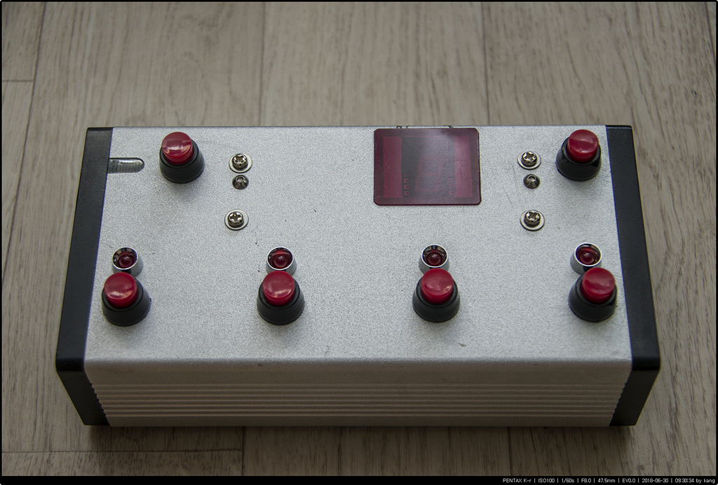
[최종완성, Final Result]

[POD 연결부, POD Connection Side]
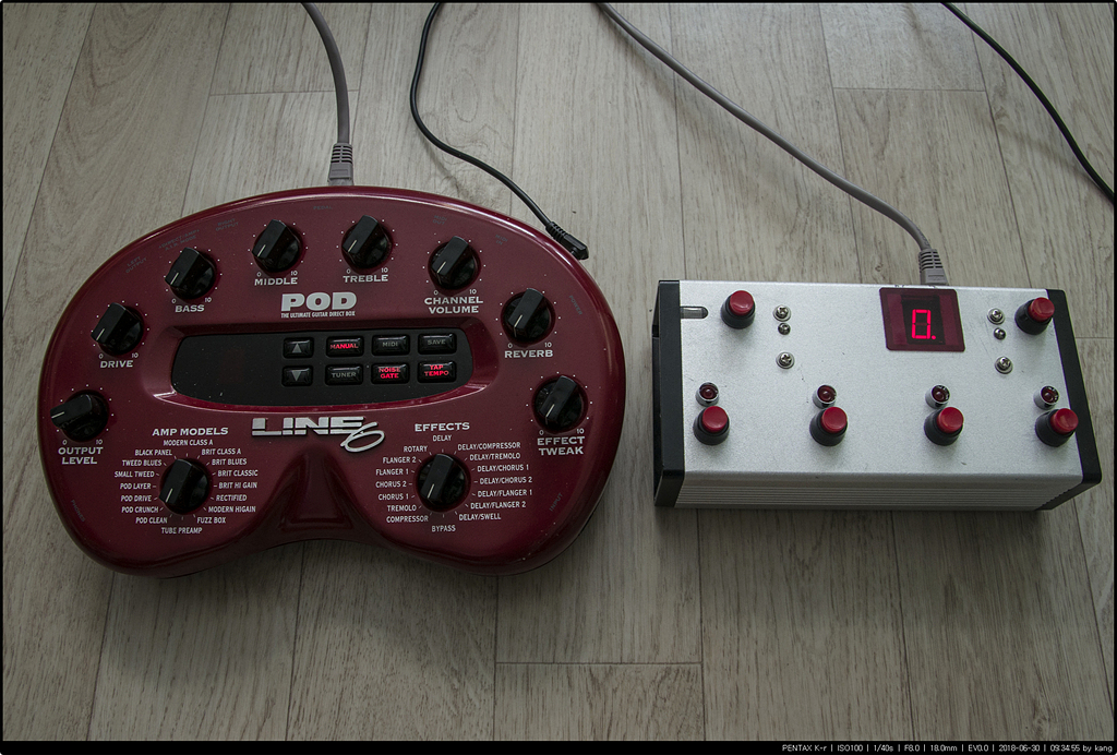
[Manual Mode]

[Channel-B at the Bank-9 in Preset Mode]

[Tuner Mode]
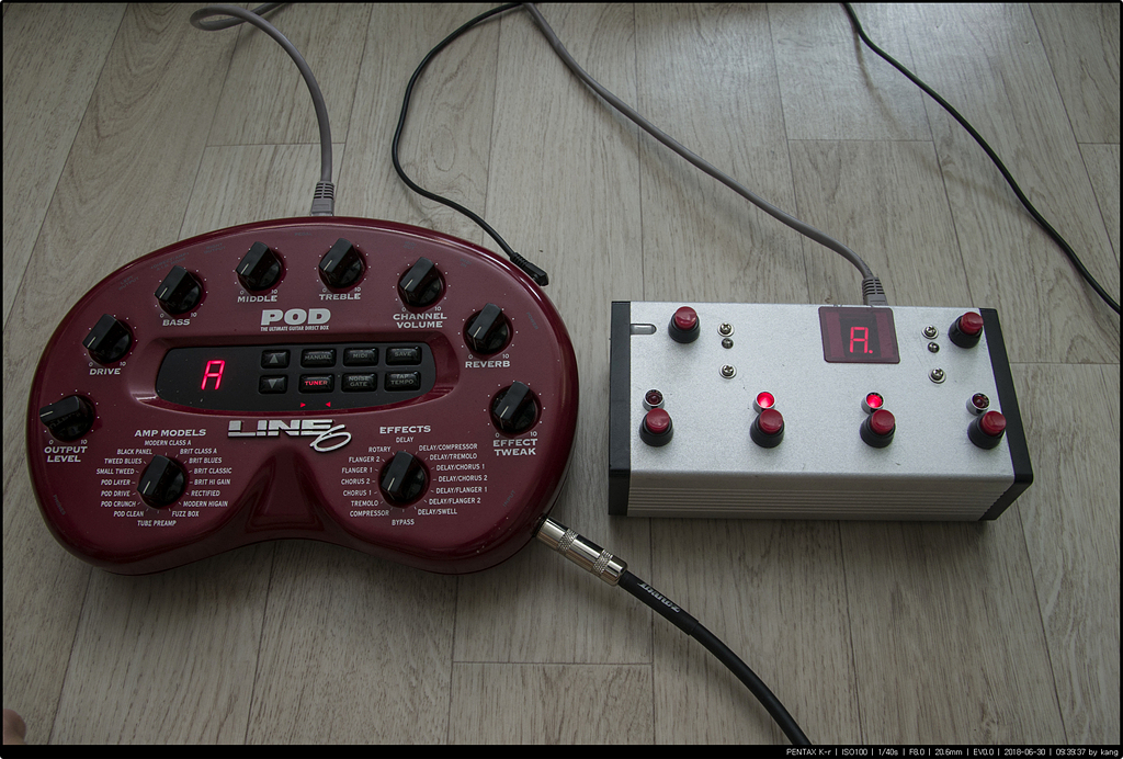
[5번줄(라) 튜닝, Tuned State with 5th(A) String]
튜너 모드에서 flat되었을때 POD에서는 flat표기를 해주지만 내 footswitch에서는 인지가 되지 않고 있다. TapTempo/Tuner LED를 flat표기로 변경해 주어야 겠다.
기타 연습은 안하고 이런거나 만들고 있음.
자작한 코드와 빌드된 헥사 파일을 첨부합니다.
115200bps 8N1으로 UART(RC7/RC6) 연결하면 문자로 동작 상태 모니터링 가능합니다.
리눅스에서 sdcc-3.6.0과 gputils-1.5.0-1로 빌드되었습니다.
개인적으로 자유롭게 사용하세요, 다만 상업적 이용은 금지합니다.
Present version of my footswitch does not display flat-pitch in tuner mode. Fortunately the POD send the flat-pitch tuned information by character 'b' by the right 7-segment LED pulse data. I'll update my code to display 'flat' through the dot-LED in 7-segment instead Tuner indication when tuner mode in someday...
I attached my code and hex file pre-built by sdcc-3.6.0 and gputils-1.5.0-1 at linux.
You may monitor the loop messages from PIC when connected with UART(RC7/RC6) at 115200bps 8N1.
You can use/modify my code/hex file freely but DO NOT use for commercial purpose.
code file: download
hex file : download