In this article, I introduce my initial test result about USB adapter for RCD-Programmer. General USB based PIC programmer has a DC/DC boost converter to make VPP voltage but the RS-232 based RCD-Programmer uses RS-232 signals to charge-pump VPP voltage and programming ICSP protocol by bit-banging. This test was started with hope to re-use my RCD-Programmer in USB. I adapted usbpicprog project for PIC programming PC application and USB protocol.
==========================================================================
+------------+ +-----------+ +--------+ +---------+
| usbpicprog +-------+ CY7C68013 +-------+ ADM213 +--------+ RCD-Pgm |
+------------+ USB +-----------+ TTL +--------+ RS-232 +---------+
| | | |
PC USB-adapter Transceiver PIC-Programmer
==========================================================================

[Fig. 1] My RCD-Programmer
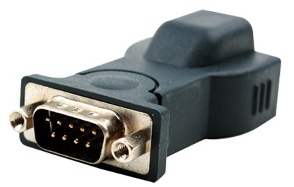
[Fig. 2] BF810 USB to Serial

[Fig. 3] PCB Top Side

[Fig. 4] PCB Bottom Side

[Fig. 5] Modification

[Fig. 6] ADM213 Pinout for BF810 and CY7C68013
RS-232 트랜시버 사용을 위해 BF810이라고 하는 USB to Serial 컨버터를 개조하여 사용 했다. [Fig. 2] 처럼 생긴놈을 분해하면 PL2303 USB 칩과 ADM213 RS-232 트랜시버 칩이 있는데 필요 없는 PL2303은 떼어 낸다. RCD-Programmer는 RS-232 신호중 TXD, DTR, RTS, CTS 신호선을 사용하므로 해당 신호선들을 찾아 CY7C68013의 PB[5:2] 포트와 연결한다. 펌웨어 개발은 일전에 공개한 debugbox 프로젝트에 포함 시켜 만들었다. AVRISP와 다르게 PIC 프로그래밍 프로토콜은 칩 모델마다 조금씩 다르게 구성 되어 있어 일반화된 프로그래밍 알고리즘 구현이 힘들다. 우선 'PIC12F629/675/PIC16F630/676 Memory Programming (DS41191D)' 메뉴얼의 프로그래밍 알고리즘을 구현하여 PIC16F676 디바이스로 테스트 해보았으며 [Fig. 8]와 같이 읽고 쓰기가 가능하였다.
I used ADM213 RS-232 transceiver from BF810 USB to Serial converter. If you disassemble the BF810, you can see PL2303 and ADM213 chip on board. Remove PL2303 and connect to PB[5:2] port of CY7C68013A. In contrast to AVRISP, PIC programming algorithms are different from device to device. My initial implementation is for 'PIC12F629/675/PIC16F630/676 Memory Programming Manual (DS41191D)' and I could successfully read and write PIC16F676 device. Initial test code was developed with my debugbox project.
I used ADM213 RS-232 transceiver from BF810 USB to Serial converter. If you disassemble the BF810, you can see PL2303 and ADM213 chip on board. Remove PL2303 and connect to PB[5:2] port of CY7C68013A. In contrast to AVRISP, PIC programming algorithms are different from device to device. My initial implementation is for 'PIC12F629/675/PIC16F630/676 Memory Programming Manual (DS41191D)' and I could successfully read and write PIC16F676 device. Initial test code was developed with my debugbox project.

[Fig. 7] Integration

[Fig. 8] PIC16F676 R/W Test Result
[] Downloads
- Pre-built firmware: Download
- Source code: Download
- just copy to debugbox project source directory and use it
댓글 없음:
댓글 쓰기